
My knowledge is based more in the software and mechanical side of things and not so much in the electronics side. So I don't think a BCD->7 Seg chip would work for my plan.


My current design has 10 leds in it and would have 11 pins. This leads me to believe that I should design it so that I only need to set the pin HIGH to create the voltage difference. I think this would require more current to flow through my circuit. In a common cathode RGB LED, the cathode of the internal LEDs are all connected to the external cathode lead. I could see that in one scenario I would need to drive both the data pin and the ground pin to be HIGH in order for no voltage to be created and thereby deactivating that segment. So if an arduino couldn't drive all of the leds then I would need to add some sort of multiplexing IC. My question to the group is this: Would it be more beneficial to make the display a common cathode or a common anode? Does it really matter? My other hope would be to string up to 6 of these together to create a clock interface (HH:MM:SS). It would be similar in concept to a 7-segment display with a small PCB and smt LEDs. I am thinking of creating a custom designed led display.
#Led anode cathode code
I am amazed by the amount of information and code available for it. I have had a great time with it since its arrival on Saturday. I am a proud new owner of an ArduinoMega.
#Led anode cathode series
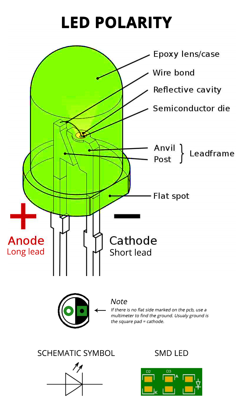
They also have many leds in series internally, so you have to be aware of their large forward voltage, 10-36V etc.I have been enjoying my time reading the wonderfully informative posts on this forum. But they are brighter and so more expensive. DX have other RGB leds that have seporate anode and cathodes for each led which makes things much easier. That would solve the issue, but you'd need to amplify the current sense voltage somehow so it's was what the IC expects. You might be able to redesign the circuit a little so the current sense resistor is on the SW pin thus making the led anode connected directly to vcc. The cathode plays the role of an electron acceptor. The anode is referred to as the positive terminal the cathode is referred to as the negative terminal. By the common cathode LED driving circuit, the shortcomings that a common anode connection method is limited by space resources of a PCB (printed circuit. So the IC current sense system will not work properly if at all. LED Anodes vs Cathodes: General Differences The anode is where electricity moves into the diode, while the cathode is where the current flows out in the other direction. So unless you plan to run each IC from an isolated supply it will create a path where the current through the sense resistor for one IC can supply power to the leds on another IC's. The DX LED has a common anode so if you connect one of the leds up to 3 of those ICs they will be all linked at that anode point. Neither the led anode or led cathode for that controller IC are connected to the supply rails. To be more confusing, For a regular diode, the pointy end is labeled the positive terminal in a general circuit diagram, but if biased in such a manner, no current flows through the diode device. Looking at that IC i dont think you'll be able to drive common anode or cathod leds from 3 of those chips. For an LED to work and emit light, one wants the current to come out of cathode, which is the pointy end in the figure. This is an electronic display device which. Common anode is used in the seven-segment displays. Since current flow is in the opposite direction of the electron flow, we see it as current flowing into anode. Because of this, electrons flow to cathode from the anode. Get the leds first so you know which type you have. Therefore, there is electron abundance on the anode compared to the cathode. However i wouldn't trust that it's the same now, they may have corrected it, or it maybe just random depending what type they have in stock when you order. The centre lead (k) is the common cathode for both LEDs, the outer leads (a1 and a2) are the anodes to the LEDs allowing each one to be lit separately, or both together to give the third colour. Note the different lengths of the three leads. Connect common anode of LED to 5V pin of Arduino (In common cathode, we connected it to GND pin). The comments were correct, the ones i got are mislabelled and are common anode. The diagram shows the construction of a tri-colour LED. Using Common Anode (CA) RGB LED with Arduino Setting up the circuit: Plug the LED in the breadboard. I bought some of those exact ones from DX about a year ago.


 0 kommentar(er)
